

Guías de Trenes en Miniatura
O Gauge Train Track: Curves, Switches and Layout Planning
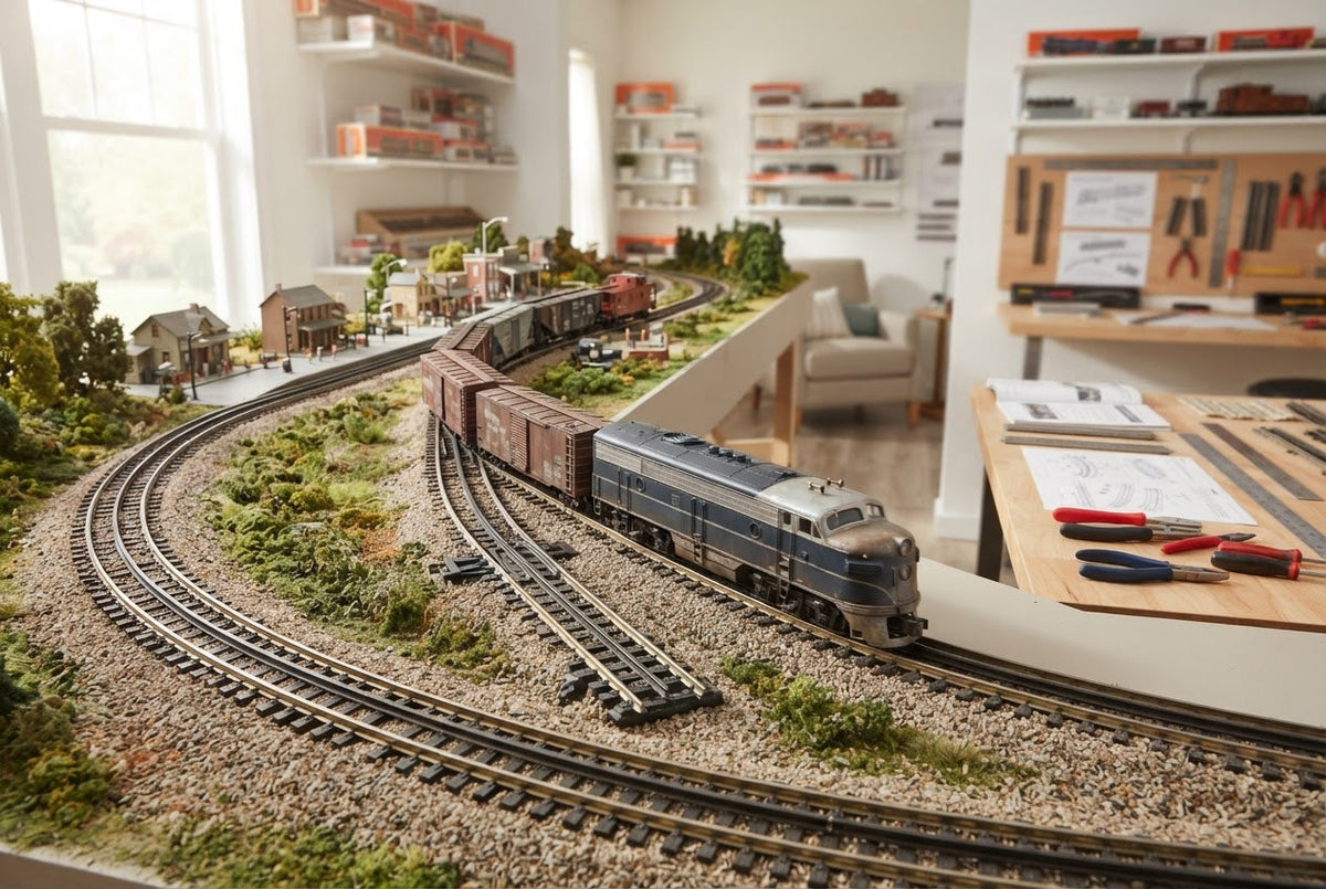
O gauge train track is the part of the railroad that decides what can run, where it can go, and how reliably it will get there. Locomotives receive the attention, but most recurring derailments, stalls, awkward scenery, and dead-end expansion plans begin with track geometry. A good layout is drawn around curve size, switch placement, access, and electrical continuity before the first building is placed.
This guide focuses on practical three-rail O gauge planning. It explains sectional curves, turnouts, clearances, grades, feeders, and expansion without assuming that one track brand fits every project. The goal is a railroad that runs smoothly on the first loop and remains understandable when a siding, bridge, station, or second train is added.
Understand O gauge train track geometry first
Sectional track is a geometry system. Curve pieces create a defined circle or diameter, straight pieces determine length, and switches introduce branches at specific angles. Mixing pieces by appearance without checking geometry often leaves a gap that cannot be solved cleanly. Begin with a scale drawing or the manufacturer’s planning template, and label every curve and straight before purchasing.
Curve designation is especially important. The number commonly associated with an O gauge curve describes the approximate diameter of the full circle in that track system, not the radius measured from the centerline in every context. Use the manufacturer’s actual dimensions when designing a table. Add clearance outside the track for locomotive pilots, long-car overhang, scenery, and hands.
Plan O gauge train track around the longest equipment
A short freight car may pass through a curve that makes a scale passenger car swing far beyond the ties. The locomotive’s wheelbase, pilot, steps, side rods, and coupler movement also affect clearance. Choose the minimum curve from the most demanding piece you intend to run, not from the smallest train currently owned.
Test opposing curves and S-curves carefully. A car leaving one curve and immediately entering the opposite curve can pull couplers sideways and derail. Insert a straight section between reverse curves where possible. On parallel tracks, increase spacing through curves so two long cars do not sideswipe. These details are difficult to repair after platforms and scenery are permanent.
Use switches to create a job for the train
A turnout turns an oval into a railroad by creating a passing siding, yard, industry spur, or alternate route. Manual switches are direct and economical when they are within reach. Remote or command-controlled switches are useful where access is limited or where route control matters. The Lionel O-36 left-hand switch and matching right-hand switch illustrate why handedness and curve family must be planned as a pair.
Do not place a switch where a bridge pier, tunnel portal, platform, or wall prevents rerailing. Leave a straight approach when possible, keep points and frogs clean, and check that pickup rollers do not bridge electrical sections incorrectly. A siding should be longer than the train it needs to hold, including clearance beyond both fouling points.
Keep power consistent around the layout
Small loops may operate from one connection, but larger railroads benefit from additional feeder wires. Rail joints carry both mechanical and electrical work; every connection adds a possible voltage drop. Run a bus beneath a permanent layout and add feeders at sensible intervals, observing the track system’s polarity conventions. Label wires before the underside becomes crowded.
Accessories should not steal power unpredictably from the train. Lighted buildings, signals, operating cars, and crossing gates may justify a separate accessory circuit. A component such as the FasTrack grade crossing with flashers should be planned with its activation and wiring requirements in mind, not treated as ordinary straight track.
Build grades and bridges conservatively
O gauge locomotives can pull impressive trains, but grades reduce capacity quickly. Keep grades gentle, provide gradual vertical transitions, and test the longest train before covering the route. A sudden change from level track to a climb can lift wheels or cause long equipment to bottom out. Curves on grades add resistance and deserve extra caution.
Bridges need straight, level approaches and solid support. The Lionel O gauge girder bridge can create a strong visual scene, but the track should remain aligned through the structure and accessible for cleaning. Never depend on scenery materials alone to hold a critical section in place.
Temporary floor loop or permanent layout
Integrated-roadbed track is convenient for temporary setups because it protects rail alignment and creates a finished appearance quickly. A floor layout should still avoid high-traffic paths, loose rugs, pet access, and furniture legs. Clean the rail and connections each time it is assembled, and store track where tabs and pins will not be bent.
A permanent layout allows bus wiring, scenery, easements, and more deliberate track placement. Before fastening anything, run trains forward and backward through every route at slow and moderate speed. Use the longest and most demanding equipment. Mark problem spots, correct them, and repeat the test. Track hidden inside a tunnel should be the most reliable track on the railroad, not the section you hope will behave.
O gauge track-planning checklist
- Draw the room, table, aisles, doors, and access openings to scale.
- Choose the minimum curve from the longest planned locomotive or car.
- Add body-overhang clearance outside curves and between parallel tracks.
- Insert straight track between reverse curves where possible.
- Place switches where points, frogs, motors, and derailed cars remain accessible.
- Plan power bus, feeders, accessory circuits, and insulated sections before scenery.
- Test grades, bridges, tunnels, and every route with the complete train.
Frequently asked questions
Can different O gauge track systems be connected?
They may be connected with purpose-built transition pieces or custom roadbed and wiring, but rail height, connector design, geometry, and appearance can differ. Plan the transition as a permanent feature rather than forcing mismatched sections together.
How often should feeder wires be added?
There is no single interval for every layout. Add feeders wherever distance, rail joints, switches, or operating load produce voltage drop. A bus-and-feeder approach is more reliable than expecting distant rail joints to carry all current.
Are tighter curves always bad?
No. Tight curves make compact layouts possible and suit traditional-size equipment designed for them. Problems arise when equipment requiring broader curves is forced through them or when overhang and parallel-track clearance are ignored.
Should track be nailed down immediately?
No. Operate the complete plan repeatedly first. Fastening track too early locks in kinks, poor switch locations, and inaccessible trouble spots.
Make O gauge train track the reliable part of the railroad
Well-planned O gauge train track disappears into the experience: the train moves smoothly, switches have a purpose, and the operator can reach every important point. That result comes from geometry, clearance, power, and testing—not from hiding joints under scenery.
Start with the longest equipment and the room’s true dimensions. Build a dependable main line, add one useful siding, wire it clearly, and prove it under operation. The rest of the railroad will be easier because its foundation makes sense.

